Atmel AVRs have a range of options to choose from when it comes to analogue-to-digital conversion making the microcontrollers extremely versatile. A number of registers in the MCU need setting to configure the ADC.
Configuration
1. Setting the ADC clock: The prescaler controls the speed of the clock source seen by the ADC and is set within the ADCSRA register.
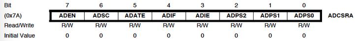
The division factor applied to the CPU clock to get the ADC clock source is determined by three bits of the ADCSRA register as shown in the table below taken from the ATmega168 datasheet:
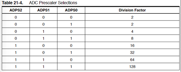
The ADC clock on the ATMmega168 needs to be between 50KHz and 200KHz. Most of my projects use external crystals of 15MHz as the microcontroller clock source, so the highest division factor of 128 gives:
15,000,000 Hz / 128 = 117,187.5 Hz
So that’s approx. 117 KHz which is within the desired range of the required ADC clock frequency. So the code for this that you will often see me use :
ADCSRA |= (1<<ADPS2) | (1<<ADPS1) | (1<<ADPS0) ;
2. Setting the ADC resolution : On the ATmega168, the ADC converts the analogue input voltage to a 10-bit digital value which is stored within two ADC data registers, ADCH and ADCL.
10-bit resolution: By default, the voltage reading is stored with the two most significant bits (ADC9 & ADC8) in the ADCH register as shown below. At this point, the ADC value is ready for use and is accessed by reading the ADCL register first which MUST be followed by reading the ADCH register (Important: the ADC Data register can not accept any new voltage readings until ADCH is read!): 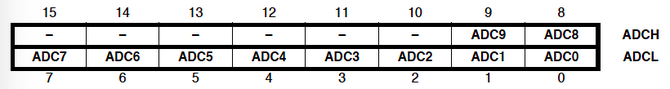 This is the default state, however, you may see the code to ensure both ADCH & ADCL registers are used for full 1024 bit resolution which is set in the ADMUX register as follows:
ADMUX &=~ (1<<ADLAR) ;
8-bit resolution: Many projects don’t require the accuracy of 10-bit resolution, which requires more CPU processing. So by setting the ADLAR bit in the ADMUX register, the voltage reading in the ADC data registers is left adjusted with the 8 most significant bits in the ADCH register as shown below: 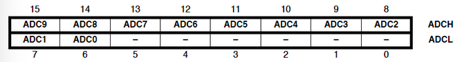 From this, only the ADCH register just needs to be read to get 8-bit resolution and ADCL can be ignored. The code to left adjust the ADC data registers (also ensuring that only the ADCH register is read) is:
ADMUX |= (1<<ADLAR) ;
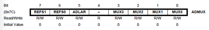
3. Choosing the ADC reference voltage : The ADC needs a maximum reference voltage to measure its readings against (it uses GND as the minimum reference voltage). The maximum voltage reference can be selected using a couple of other bits in the ADMUX register. The table below indicates which voltage references can be used: 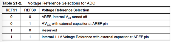 By default the AREF pin in the MCU is used as the reference voltage so needs to be tied to the 5V power line. However, if you are working on a sensitive application, selecting one of the other references might provide a reference with less background noise. I often select the AVCC pin of the AVR and the code to do this is:
ADMUX |= (1<<REFS0) ;
4. Interrupt-based ADC : I routinely use an interrupt-based ADC where an interrupt subroutine is initiated every time the ADC completes a conversion. The code to enable the interrupt function of the ADC is:
ADCSRA |= (1<<ADIE) ;
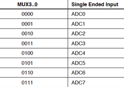
5. Choosing the ADC channels : The ATmega168 microcontroller can perform its ADC function on several of its pins. The ADC0 channel (pin 23 / PORTC0) is the default channel and your analogue voltage should be connected to it. However other pins / ports can be selected by changing some of the bits within the ADMUX register:![]()
Activation
1. Turning on the ADC : The ADC will begin consuming power as soon as the ADEN bit of the ADCSRA register is set to 1, so it is recommended that the ADC is turned on just before needing to start a conversion. The code for this is:
ADCSRA |= (1<<ADEN) ;
2. Starting a conversion : The analogue-to-digital conversion begins as soon as the ADSC bit of the ADCSRA register is set to 1.
ADCSRA |= (1<<ADSC) ;
When the conversion is over, the AVR automatically clears the ADSC bit ready for the start of another conversion.
Calculation
Using 10-bit resolution, the equation to calculate the measured voltage is:
V = (ADC result x voltage reference) / 1024
For 8-bit resolution, the equation to calculate the measured voltage is:
V = (ADC result x voltage reference) / 255