The RFM12B 433MHz (sometimes called TRX433S) wireless module is used in several of my projects for close range wireless communication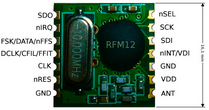 . Using it is pretty straightforward once it’s set up. In fact, I have a couple of these units permanently set up on separate breadboards which I use for the initial prototyping of almost all the projects that require a wireless component. In this section, I will outline some of the details around using them.[easyazon_cta add_to_cart=”default” align=”right” asin=”B007XEX19I” cloaking=”default” height=”28″ key=”wide-light” localization=”default” locale=”UK” nofollow=”default” new_window=”default” tag=”tronic03-21″ width=”170″]
The modules communicate with the AVR microprocessor using Serial Peripheral Interface (SPI). That means you need a circuit connection set up something like this: 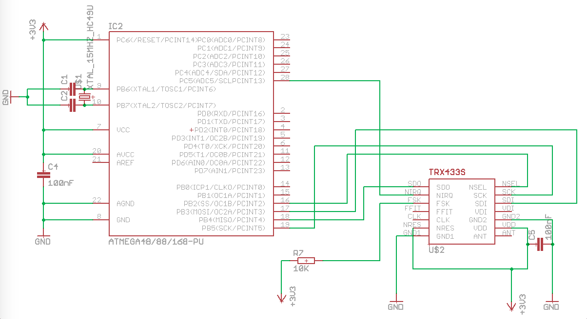 Setting up the circuit is the easy part – programming the AVR to control the RFM12B module is where the real work begins! Fortunately, a lot of the programming has been done for us, and it is just a matter of incorporating it into your project. I find it helps if there is a detailed explanation of what’s happening during the program. So here goes:
First off, the whole program is based around a macro defined in the RF.c file where a hexadecimal (2 byte) command code that the RFM12B understands is sent to the module from the AVR. For example, the hexadecimal number 32CA (represented as 0x32CA), made up of the Most Significant Byte (MSB) ’32’ and the Least Significant Byte (LSB) ‘CA’. This would look like ‘RFXX_WRT_CMD (0x32CA)’ in the C program and is defined in the macro as follows:
RFXX_WRT_CMD (0x32CA)
{unsigned int fifodata;
unsigned char LSB, MSB, fifomsb, fifolsb;
LSB = (0x32CA & 0xFF); // read the ‘CA’ portion of the command
MSB = ((0x32CA >> 8) & 0xFF); // read the ’32’ portion of the command
here is where you start transmission: the SS pin is driven LOW to select the RFM12B as the slave in the SPI communication protocol
PORTB &= ~(1<<PB2); // PB2 (aka. SS pin of the AVR) is connected to the nSEL (‘selection’) pin of the RFM12B module
SPDR = MSB; // transmission is initiated by placing MSB (defined previously) into the SPI Data Register (SPDR) of the AVR
while(!(SPSR & (1<<SPIF))); // this makes the AVR wait for transmission of the MSB from the SPDR to end
fifomsb = SPDR; // as part of the SPI protocol the equivalent register on the RFM12B exchanges its own byte and places it into the SPDR register as outlined in the diagram below. This is then assigned to the variable ‘fifomsb’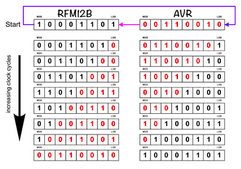
SPDR = LSB; // the LSB is transmitted next by placing it into the SPDR
while(!(SPSR & (1<<SPIF))); // once again the AVR waits for transmission of the LSB to end
fifolsb = SPDR; // and once again the byte in the RFM12B register is exchanged, this time assigned to ‘fifolsb’
PORTB |= (1<<PB2); // the SS pin is then driven HIGH to indicate the end of the packet of data exchange
fifodata = ((fifomsb<<8)+fifolsb); // the two bytes received from the RFM12B are concatenated together and assigned to ‘fifodata’
return fifodata;
}
Configuration
Before any wireless transmission can occur, some configuration of the AVR and RFM12B is required. The first step involves initializing the AVR pins for communication with the wireless module (the macro is also defined in the linked RF.c file)
RFXX_PORT_INIT()
{
set MOSI and SCK and SS pins as outputs for SPI communication between AVR and wireless module
DDRB = (1<<DDB3)|(1<<DDB5)| (1<<DDB2);
enable SPI and Master and set the clock rate to fck/16
SPCR = (1<<SPE)|(1<<MSTR)|(1<<SPR0);
set the AVR pin that is connected to nIRQ (in this case PC5) as an input
DDRC &=~(1<<5);
disable the pull up on AVR pin PC5 (since it will be controlled by the wireless module)
PORTC&=~(1<<5);
}
then you move into the meat of the program which is the main ‘for’ loop. The first thing to do here is to initialize the wireless module to act as a receiver.
Reception mode
RF12_INIT_Receiver();
{
RFXX_WRT_CMD(0x80D7); – EL,EF,433band,11.5pF
RFXX_WRT_CMD(0x82D9); – er,ebb,!ET,ES,EX,!eb,!ew,DC (receiver-specific)
RFXX_WRT_CMD(0xA640); – 434MHz
RFXX_WRT_CMD(0xC647); – 4.8kbps
RFXX_WRT_CMD(0x94D8); – VDI,FAST,134kHz,0dBm,-103dBm
RFXX_WRT_CMD(0xC2AC); – AL,!ml,DIG,DQD4
RFXX_WRT_CMD(0xCA81); – FIFO8,SYNC,!ff,DR
RFXX_WRT_CMD(0xC483); – @PWR,NO RSTRIC,!st,!fi,OE,EN
}
after that, you need to enable the type of communication the module will perform – in this case, First In, First Out (FIFO). This is done by sending the hexadecimal command CA83 to the wireless module
RFXX_WRT_CMD(0xCA83);
set the ChkSum variable to zero – this is for error checking later
ChkSum=0;
at this point the wireless module is ready to receive wireless data, so the AVR then sits and waits for the wireless module to indicate that it has received some data. Programmatically, this is incorporated within a ‘for’ loop so that several bytes of data (in this example, 3 bytes) can be retrieved from the wireless module as they come in off the air.
for(z=0;z<3;z++)
{
cData = RF12_RECV();
ChkSum+= cData;
}
The RF12_RECV(); macro is key here and is defined in RF.c as follows:
unsigned char RF12_RECV(void)
{
unsigned int FIFO_data; // this is the variable where the data byte will be stored
while(PINC&(1<<5)); // wait for the nIRQ pin of the RF module to drive LOW before moving to the next line in the macro
RFXX_WRT_CMD(0x0000); // get the RF module to read its status register (a necessary standard procedure)
FIFO_data=RFXX_WRT_CMD(0xB000); // send a read command to the RF module and the returned is the data byte we want
return(FIFO_data&0x00FF); // returns the data byte that has just been read
}
[A note about the ‘ while(PINC&(1<<5)); ‘ loop as it is easy to get confused as to what it’s doing exactly. As with other ‘while’ loops, it repeats as long as it is (boolean) true, ie. when it reads as ‘while(1)’, the loop will … well loop! As soon as it is false, i.e. once it reads as while(0), the loop will end. So you may ask what operation does it perform when it is looping? The answer is nothing because there are no curly brackets to indicate what to do during the loop, so essentially it just keeps looping asking the same question: ‘am I true (1) or false (0)?’ Specifically, in this code the outcomes are as follows:
When nIRQ is high (1) translates to ‘while(1)’ so the loop keeps looping and we stay put
When nIRQ is low (0) translates to ‘while(0)’ so the loop ends and the program moves to the next line
so no confusion hopefully….. yeah right!]
So going back to the ‘for’ loop for receiving data bytes, as each of them arrive from the wireless module, they are assigned to a variable ‘cData’, and are added together within another variable, ‘ChkSum’, for later error checking.
A 4th byte is then received and placed in the variable ‘j’
j=RF12_RECV();
Once the 4 bytes of data have been transmitted from the RFM12B, it is then disabled using the hexadecimal command CA81:
RFXX_WRT_CMD(0xCA81);
Now for some error checking: The 4th byte’s value was calculated before wireless transmission as the sum of the 3 data bytes. If all has gone well with the transmission of the 3 data bytes, then the 4th byte should still be equal to the sum of the 3 data bytes at the receiver’s end. If any of the databytes have been garbled or lost during transmission, their sum will not equal the value of the 4th byte. The code to check this is simply a boolean ‘if’ statement:
if (ChkSum==j)
{…}
If the variable ChkSum is equal to j (ie. the sum of the databytes is correct), then the answer to the ‘if’ statement is ‘true’ and the code within the curly brackets will execute (in this case LEDs on AVR pins PD6 and PD7 will flash in a specific sequence).
Transmission mode
To ensure the wireless module only begins transmitting when it has the necessary data, we use another set of ‘if” statements to control events
if (state == IDLE )
{
….do some work providing data for transmission….and then when finished change variable ‘state’ to ‘updated’…
state=UPDATED;
}
When the AVR finishes the work we have told it to perform, it can then deal with the transmission of any data in the next ‘if” statement. The first line within this ‘if’ statement changes the wireless module into transmit mode, followed by transmission of the data and then setting the AVR back to its ‘idle’ state
if (state==UPDATED)
{RF12_INIT_transmitter();
Transmit(…some data….);
state=IDLE;
}
The initialization-as-a-transmitter macro incorporates a series of commands sent to the wireless module
RF12_INIT_transmitter();
{
RFXX_WRT_CMD(0x80D7); – EL,EF,433band,12.0pF
RFXX_WRT_CMD(0x8239); – !er,!ebb,ET,ES,EX,!eb,!ew,DC
RFXX_WRT_CMD(0xA640); – A140=430.8MHz
RFXX_WRT_CMD(0xC647); – 4789bps
RFXX_WRT_CMD(0x94A0); – VDI,FAST,134kHz,0dBm,-103dBm
RFXX_WRT_CMD(0xC2AC); – AL,!ml,DIG,DQD4
RFXX_WRT_CMD(0xCA81); – FIFO8,SYNC,!ff,DR
RFXX_WRT_CMD(0xC483); – @PWR,NO RSTRIC,!st,!fi,OE,EN
RFXX_WRT_CMD(0x9820); – !mp,9810=30kHz,MAX OUT
RFXX_WRT_CMD(0xE000); – NOT USE
RFXX_WRT_CMD(0xC800); – NOT USE
}
This is followed by the transmission sequence of the data
Transmit (…some data…)
{
RFXX_WRT_CMD(0x0000); – read status register
RFXX_WRT_CMD(0x8239); – !er,!ebb,ET,ES,EX,!eb,!ew,DC (power management command)
RF12_SEND(0xAA); – PREAMBLE
RF12_SEND(0xAA); – PREAMBLE
RF12_SEND(0xAA); – PREAMBLE
RF12_SEND(0x2D); – SYNC HI BYTE
RF12_SEND(0xD4); – SYNC LOW BYTE
RF12_SEND(…data….); – DATA BYTE
RF12_SEND(…data…); – DATA BYTE 1
RF12_SEND(0xAA); – DUMMY BYTE
RF12_SEND(0xAA); – DUMMY BYTE
RF12_SEND(0xAA); – DUMMY BYTE
RFXX_WRT_CMD(0x8201); – disables power to the RF module (sleep)
_delay_ms (200);
}
Actually sending a byte of data involves a separate macro (also located in the RF.c file)
RF12_SEND(aByte)
{
here the program waits for the nIRQ pin to indicate that no other transmission is currently in progress or that the previous transmission has finished
while(PINC&(1<<5));
and then it sends the next byte which involves the hexadecimal send command B8 combined with the data byte (i.e. B8xx).
RFXX_WRT_CMD(0xB800+aByte);
}
To be continued …